Showing posts with label Orbiter. Show all posts

Tuesday, February 11, 2014

ESA Mars Express orbiter reveals overflowing craters

Credit: ESA/DLR/FU Berlin (G. Neukum)

Large and small, hundreds of thousands of craters scar the surface of Mars, hollowed out by a multitude of asteroids and comets that impacted the Red Planet throughout its history.

This image shows a region of the planet's northern hemisphere known as Hephaestus Fossae – after the Greek god of fire – that was imaged by the high-resolution stereo camera on ESA's Mars Express orbiter on 28 December 2007.

The image has been coloured to indicate the elevation of the terrain: green and yellow shades represent shallow ground, while blue and purple stand for deep depressions, down to about 4 km.

Scattered across the scene are a few dozen impact craters that cover a wide range of sizes, with the largest boasting a diameter of around 20 km.

The long and intricate canyon-like features that resemble riverbeds are the phenomenal aftermath of the same fierce impacts that created the largest craters.

When a small body such as a comet or an asteroid crashes at high speed into another object in the Solar System, the collision dramatically heats up the surface at the impact site.

In the case of the large crater seen in this image, the heat produced by such a powerful smash melted the soil – a mixture of rock, dust and also, hidden deep down, water ice – resulting in a massive overflow that flooded the surrounding environment.

Before drying up, this muddy fluid carved a complex pattern of channels while making its way across the planet's surface.

The melted rock–ice mixture also gave rise to the fluidised appearance of the debris blankets surrounding the largest crater.

Based on the lack of similar structures near the small craters in this image, scientists believe that only the most powerful impacts – those responsible for forging the largest craters – were able to dig deep enough to release part of the frozen reservoir of water lying beneath the surface.

Tuesday, December 13, 2011

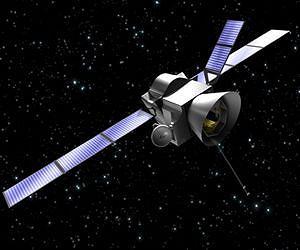
ESA BepiColombo Mercury Magnetospheric Orbiter: Structural model

The four components of the Mercury Composite Spacecraft together for the first time in the 'Rosetta' cleanroom at ESA's European Space Research and Technology Centre in Noordwijk, the Netherlands on 14 November 2011. 

Front right, on its ground multi-purpose trolley - the Mercury Planetary Orbiter (MPO) Structural and Thermal Model. 

Front left, on its handling trolley - the Mercury Magnetospheric Orbiter (MMO) Structural Model. 

Rear left, on its multi-purpose trolley - the Mercury Transfer Module (MTM) Structural and Thermal Model. 

Rear right - Magnetospheric Orbiter Sunshade and Interface Structure (MOSIF) Proto-Flight Model, in two parts - the sunshade (left, on the floor) and the interface adapter (right, on the vertical integration stand).

The BepiColombo Mercury Magnetospheric Orbiter Structural Model arrived at ESA's European Space Research and Technology Centre in the Netherlands on 7 November 2011, having been flown from Japan.

In the coming weeks, the four components that make up the Mercury Composite Spacecraft will be prepared for integration into their launch configuration in preparation for an acoustic and mechanical test campaign.

The BepiColombo Mercury Magnetospheric Orbiter (MMO) Structural Model (SM) arrived at ESA's European Space Research and Technology Centre (ESTEC) in Noordwijk, the Netherlands, on 7 November 2011, having travelled by road from Amsterdam Airport Schiphol.

The spacecraft, which is being developed and built by the Japan Aerospace Exploration Agency (JAXA), was flown from their facility at Sagamihara, Japan.

Once the transport container had been cleaned and transferred to the 'XMM' cleanroom in the ESTEC Test Centre, it was left overnight to reach thermal equilibrium with its surroundings.

On 8 November, the transport container was opened and the MMO's internal shock recorders were inspected to ensure that the dynamic environment experienced by the spacecraft during transport had remained within specifications.

An overhead crane and lifting device were used to move the MMO from its transport container base onto its handling trolley, after which it was moved to the 'Rosetta' cleanroom to join the other components of the Mercury Composite Spacecraft (MCS).

In parallel with the unpacking of the MMO, the Mercury Planetary Orbiter (MPO) was undergoing alignment checks after completion of its thermal balance test and the removal of its thermal blankets.

In the coming weeks, the MMO, the MPO, the Mercury Transfer Module (MTM) and the Magnetospheric Orbiter Sunshade and Interface Structure (MOSIF) will be prepared for integration to form the MCS, the configuration in which they will be launched and travel to Mercury.

The BepiColombo Mission

BepiColombo is Europe's first mission to Mercury. It is scheduled to launch in 2014 and arrive at Mercury in late 2020. It will endure temperatures in excess of 350C and gather data during a one-year nominal mission, with a possible one-year extension.

The mission comprises two spacecraft: the Mercury Planetary Orbiter (MPO) and the Mercury Magnetospheric Orbiter (MMO). During the journey to Mercury, the MMO will be shielded from the Sun by the Magnetospheric Orbiter Sunshield and Interface Structure (MOSIF), which also provides the interface between the MMO and the MPO.

The fourth component of the composite spacecraft stack is the Mercury Transfer Module (MTM), whose primary task is to provide solar-electric propulsion for the journey to Mercury.

BepiColombo is a joint mission by ESA and the Japan Aerospace Exploration Agency (JAXA), executed under ESA leadership. The Prime Contractor for BepiColombo is Astrium GmbH.

Tuesday, November 1, 2011

ESA BepiColumbo Mercury Mission: Surviving a Heat Sandwich - Video


Set to launch in 2014, Europe's BepiColumbo satellite pair will deliver unique imagery of Mercury during extra-close orbital passes.

The pair will contend with extreme temperatures from the nearby Sun and bright reflections from Mercury's surface.
Credit: ESA

Tuesday, October 18, 2011

ESA Mercury Planetary Orbiter: simulated trip to Mercury


The Structural and Thermal Model (STM) of the BepiColombo Mercury Planetary Orbiter (MPO) in the Large Space Simulator (LSS) at ESA's Test Centre in Noordwijk, the Netherlands. 

The MPO is mounted on the LSS gimbal stand / spin box and levelling table that support, orient, rotate and level the spacecraft during testing. 

The MPO is being prepared for thermal-balance testing. Copyright: ESA/Anneke Le'Floch.

Thermal-balance testing of the BepiColombo Mercury Planetary Orbiter Structural and Thermal Model, which has been under way in ESA's Large Space Simulator since 20 September, has been successfully completed.

During these tests the conditions the spacecraft will encounter during the cruise to Mercury and while in orbit have been simulated, and a number of tests to characterise the spacecraft performance under some worst-case scenarios have been carried out.

'Dry run' in the Large Space Simulator
Following the installation of the Mercury Planetary Orbiter (MPO) Structural and Thermal Model (STM) in the Large Space Simulator (LSS) at ESA's Test Centre in Noordwijk, the Netherlands on 31 August and the completion of all the necessary preparations, a 'dry run' was conducted on 13 September to verify the performance of the spacecraft, its instrumentation, and the gimbal stand / spin box and levelling table that support, orient, rotate and level the spacecraft during testing.

The dry run was performed with the LSS top cover open; the MPO was illuminated with just one of the nineteen 25-kW lamps that make up the solar simulator.

To reach the radiation intensity that the orbiter will experience in orbit around Mercury, the 121 hexagonal mirror segments that produce the beam have been adjusted to produce a converging beam rather than the standard parallel beam.

To allow the wall of the LSS to cope with the increased beam intensity while continuing to simulate the cold of space, an additional shroud has been installed.

Pump down and cold calibration
After the dry run, the LSS top hatch was closed and vacuum pumping commenced on 20 September.

Once a vacuum of around 10-5 mbar had been achieved, liquid nitrogen started to be pumped through the shrouds of the chamber walls to cool the interior of the LSS down to less than -173 degrees C (100 K).

Once cool-down was completed, the steady state under cold conditions (referred to as 'cold calibration') was achieved and baseline data were acquired.

Cruise and orbit

On 22 September, simulation of the initial cruise phase of MPO's journey to Mercury began.

This was followed, the next day, by the intermediate cruise phase; testing under in-orbit conditions followed, beginning on 26 September with conditions at aphelion and then moving on to perihelion.

Particular attention has been paid to conditions at perihelion, where the MPO will be most strongly illuminated.

Investigations of the spacecraft's thermal performance during entry into and exit from eclipse have also been also carried out through 'snapshots' at various attitudes (for example, rotation of 45 degrees with the Sun on the +Y/-X faces and tilting of 30 degrees with the Sun on the +Z/+Y faces).

Around 4000 litres of liquid nitrogen are consumed per hour during testing, so a steady stream of tankers have been arriving to replenish the 100 000-litre on-site storage capacity.

The heaters that simulate the thermal dissipation of the electronics units and those that warm critical components during eclipse are powered by external power sources during testing.

Temperature data, obtained using thermocouples, are acquired by the thermal data handling system that is part of the LSS.

Two infrared cameras are used to monitor the spacecraft's multi-layer insulation and items external to the satellite that face the Sun simulator.

To maintain realistic conditions for the heat pipe network, which is designed to work in the microgravity of Mercury orbit, the satellite is kept levelled by adjusting the levelling table and acquiring readings from on-board tilt meters.

Non-nominal attitude - testing the worst-case scenario

Friday, October 14, 2011

ESA BepiColombo: Mercury Planetary Orbiter takes a simulated trip to the innermost planet

Thermal-balance testing of the BepiColombo Mercury Planetary Orbiter Structural and Thermal Model, which has been under way in ESA's Large Space Simulator since 20 September, has been successfully completed.

During these tests the conditions the spacecraft will encounter during the cruise to Mercury and while in orbit have been simulated, and a number of tests to characterise the spacecraft performance under some worst-case scenarios have been carried out.

'Dry run' in the Large Space Simulator
Following the installation of the Mercury Planetary Orbiter (MPO) Structural and Thermal Model (STM) in the Large Space Simulator (LSS) at ESA's Test Centre in Noordwijk, the Netherlands on 31 August.

The completion of all the necessary preparations, a 'dry run' was conducted on 13 September to verify the performance of the spacecraft, its instrumentation, and the gimbal stand / spin box and levelling table that support, orient, rotate and level the spacecraft during testing.

The dry run was performed with the LSS top cover open; the MPO was illuminated with just one of the nineteen 25-kW lamps that make up the solar simulator.

To reach the radiation intensity that the orbiter will experience in orbit around Mercury, the 121 hexagonal mirror segments that produce the beam have been adjusted to produce a converging beam rather than the standard parallel beam.

To allow the wall of the LSS to cope with the increased beam intensity while continuing to simulate the cold of space, an additional shroud has been installed.

Pump down and cold calibration
After the dry run, the LSS top hatch was closed and vacuum pumping commenced on 20 September. Once a vacuum of around 10-5 mbar had been achieved, liquid nitrogen started to be pumped through the shrouds of the chamber walls to cool the interior of the LSS down to less than -173 degrees C (100 K).

Once cool-down was completed, the steady state under cold conditions (referred to as 'cold calibration') was achieved and baseline data were acquired.

Monday, July 4, 2011

NASA Orbiter Processing Facilities: High-Tech Shuttle Garages

Columbia towed into OPF

Image: Shuttle Columbia arrived at Kennedy's Shuttle Landing Facility via the shuttle carrier aircraft in March 1979 after completing its ferry flight from Dryden Flight Research Center in California. Columbia then was towed into an OPF for processing for STS-1, NASA's first shuttle fight. Photo credit: NASA
› Larger image


If home is where the heart is, then the heart and soul of NASA's space shuttle fleet reside in three custom-built, 29,000-square-foot buildings at Kennedy Space Center in Florida.

They're formally called orbiter processing facilities (OPF), but routinely go by the names OPFs, bays, or hangars, and inside highly experienced technicians perform two-thirds of the work to prepare a shuttle for space.

The bays may be the highest-tech garages on the planet, where workers ready a spaceship for flight without scuffing it and huge cranes move tons of cargo into place. But it's also a place where staples are prohibited from the paperwork technicians work off of so the little pieces of metal don't accidentally become embedded in the shuttle's critical systems.

Fresh off Kennedy's Shuttle Landing Facility and back from a mission, shuttles are towed to their individual processing bays. In recent years, OPF-1 and OPF-2, which are connected by a 233-foot-long low bay, have been the residence of Atlantis and Endeavour, respectively. Across the street is OPF-3, the home base of Discovery. Once inside, technicians jack-and-level the shuttle to maintenance height where platforms and a main access bridge surround the spacecraft like a glove.

"Each high bay has a footprint of the orbiter, and when it rolls in, it has to fit to that footprint," said Wayne Bingham, a United Space Alliance, or USA, flow manager.

"We try to keep the platforms within a maximum distance of 6 to 8 inches, but a minimum of 4 inches."

NASA - Orbiter Processing Facilities: High-Tech Shuttle Garages


Spacelab in Columbia payload bay

Image: In September 1983, technicians in Orbiter Processing Facility-2 inspect Spacelab-1 in the payload bay of shuttle Columbia. Photo credit: NASA
› Larger image


Endeavour in OPF-2 Image: In OPF-2, technicians check out space shuttle Endeavour's payload bay before its final mission, STS-134. Photo credit: NASA/Frankie Martin
› Larger image

Discovery is towed into OPF-2 for retirement processing Image: Shuttle Discovery's tail fin clears the hangar door of Orbiter Processing Facility-2 at the end of its 39th and final spaceflight mission, STS-133 in March 2011. Inside the OPF, Discovery will be prepared for future public display. Photo credit: NASA/Kim Shiflett
› Larger image

Atlantis is prepared for STS-135 and final mission in OPF-1 Image: Workers watch as shuttle Atlantis slowly backs out of OPF-1 during its rollover to the Vehicle Assembly Building for its final mission, STS-135. Photo credit: NASA/Jack Pfaller
› Larger image

Thursday, May 26, 2011

NASA EVA: Orbiter Boom Sensor System

The space shuttle's robotic arm released the Orbiter Boom Sensor System at 12:50 a.m., and it was stowed as a permanent part of the space station at 1:42 a.m.

Mike Fincke will connect two grounding connectors, while Greg Chamitoff installs a foot restraint on the station’s robotic arm for use later in the spacewalk.

Currently, a grapple fixture in the middle of the boom is the only one the station arm is able to use, which halves the reach of the boom when on the station’s arm.

To remedy this, the spacewalkers will replace an electrical flight grapple fixture currently on one end of the boom with a power and data grapple fixture the station arm can use.

Once the power and data grapple fixture is added, it will be known as the Enhanced International Space Station Boom Assembly.

Both Mike Fincke and Greg Chamitoff will make their way to the P6 segment of the station’s truss to retrieve the power and data grapple fixture. To retrieve it, Fincke and Chamitoff will work together to release four bolts holding it in place. Chamitoff will then climb onto the station’s robotic arm for a ride back to boom on the starboard side of the station’s truss.

Chamitoff, with assistance from Fincke, will release the six bolts holding the electrical flight grapple fixture to the boom and cut its cable. Then he will install an adapter assembly on the boom, using six bolts and slide the power and data grapple fixture into place on it. Four bolts will hold it in place.

Wednesday, December 22, 2010

NASA Cassini's Dramatic Views Of Rhea


Newly released for the holidays, images of Saturn's second largest moon Rhea obtained by NASA's Cassini spacecraft show dramatic views of fractures cutting through craters on the moon's surface, revealing a history of tectonic rumbling.

The images are among the highest-resolution views ever obtained of Rhea.

"These recent, high-resolution Cassini images help us put Saturn's moon in the context of the moons' geological family tree," said Paul Helfenstein, Cassini imaging team associate, based at Cornell University, Ithaca, N.Y.

"Since NASA's Voyager mission visited Saturn, scientists have thought of Rhea and Dione as close cousins, with some differences in size and density. The new images show us they're more like fraternal twins, where the resemblance is more than skin deep. This probably comes from their nearness to each other in orbit."

Cassini scientists designed the March 2010 and November 2009 encounters in part to search for a ring thought to encircle the moon. During the March flyby, Cassini made its closest- approach to Rhea's surface so far, swooping within 100 kilometers (62 miles) of the moon.

Based on these observations, however, scientists have since discounted the possibility that Rhea might currently have a faint ring above its equator.

These flybys nonetheless yielded unique views of other features on the moon, including ones that are among the best ever obtained of the side of Rhea that always faces away from Saturn.

Other views show a web of bright, "wispy" fractures resembling some that were first spotted on another part of Rhea by the two Voyager spacecraft in 1980 and 1981.

At that time, scientists thought the wispy markings on the trailing hemispheres - the sides of moons that face backward in the orbit around a planet - of Rhea and the neighboring moon Dione were possible cryovolcanic deposits, or the residue of icy material erupting. The low resolution of Voyager images prevented a closer inspection of these regions.

Monday, August 2, 2010

COMPASS GPS: China successfully launched its fifth orbiter


The fifth orbiter into space, as part of its satellite navigation and positioning network known as Beidou, or Compass system, is launched on the Long March 3I carrier rocket at Xichang Satellite Launch Center in Xichang, southwest China's Sichuan Province, on August 1, 2010. (Xinhua/Du Cai)


China successfully launched its fifth orbiter into space at 5:30 a.m. Sunday, as a part of its indigenous satellite navigation and positioning network.

The satellite was launched from the Long March 3I carrier rocket.

It is the 126th flight for the country's Long March series of rockets.

The satellite will join another four satellites in orbit to form a network that will eventually consist of 35 satellites.

The system, code named "COMPASS", is a crucial part of the country's space infrastructure for providing navigation and positioning services in transportation, meteorology, petroleum prospecting, forest fire monitoring, disaster forecast, telecommunications and public security among others.

China started building its own satellite navigation system to end its dependence upon the U.S. GPS system in 2000, when it sent two orbiters as a double-satellite experimental positioning system.

The system is designed to provide navigation, time and short message services in the Asia and Pacific region before 2012 and will be capable of providing global navigation services by 2020.

Friday, March 5, 2010

NASA Mars Orbiter: Inverted crater in Arabia Terra

An inverted crater in the Arabia Terra region of Mars that is among the images taken by NASA's Mars Reconnaissance Orbiter.

NASA said the orbiter has sent back 100 terabits of information since 2006. That's equal to about 3 million songs in MP3 format

Picture: NASA

Saturday, December 5, 2009

NASA MARS: Odyssey Orbiter goes into Safe Standby Mode

NASA's Mars Odyssey orbiter put itself into a safe standby mode on Saturday, Nov. 28, and the team operating the spacecraft has begun implementing careful steps designed to resume Odyssey's science and relay operations within about a week.

Engineers have diagnosed the cause of the Nov. 28 event as the spacecraft's proper response to a memory error with a known source. The likely cause is an upset in the orbiter's "memory error external bus," as was the case with a similar event in June 2008.

In safe mode over the weekend, Odyssey remained in communication with ground controllers and maintained healthy temperatures and power. To clear the memory error, the team commanded Odyssey today to perform a cold reboot of the orbiter's onboard computer. The spacecraft reported that the reboot had been completed successfully.

"This event is a type we have seen before, so we have a known and tested path to resuming normal operations," said Odyssey Project Manager Philip Varghese of NASA's Jet Propulsion Laboratory, Pasadena, Calif.

Odyssey has been orbiting Mars since 2001. In addition to its own major scientific discoveries and continuing studies of the planet, the Odyssey mission has played important roles in supporting the missions of the Mars rovers Spirit and Opportunity and the Phoenix Mars Lander.

Until Odyssey is available again as a communications relay, Spirit and Opportunity will be operating with direct communications to and from Earth.

Friday, September 25, 2009

NASA Mars Reconnaissance Orbiter - Meteorites expose water

http://www.nasa.gov/images/content/388887main_mars_ice_690x226.jpg
NASA's Mars Reconnaissance Orbiter has revealed frozen water hiding just below the surface of mid-latitude Mars. The spacecraft's observations were obtained from orbit after meteorites excavated fresh craters on the Red Planet.

Scientists controlling instruments on the orbiter found bright ice exposed at five Martian sites with new craters that range in depth from approximately half a meter to 2.5 meters (1.5 feet to 8 feet). The craters did not exist in earlier images of the same sites. Some of the craters show a thin layer of bright ice atop darker underlying material. The bright patches darkened in the weeks following initial observations, as the freshly exposed ice vaporized into the thin Martian atmosphere. One of the new craters had a bright patch of material large enough for one of the orbiter's instruments to confirm it is water-ice.

The finds indicate water-ice occurs beneath Mars' surface halfway between the north pole and the equator, a lower latitude than expected in the Martian climate.

"This ice is a relic of a more humid climate from perhaps just several thousand years ago," said Shane Byrne of the University of Arizona, Tucson.

Byrne is a member of the team operating the orbiter's High Resolution Imaging Science Experiment, or HiRISE camera, which captured the unprecedented images. Byrne and 17 co-authors report the findings in the Sept. 25 edition of the journal Science.